Micro computing with the GMC-4
“Made it! And with one and a half bytes left to spare!”
I was down in San Francisco’s Japantown a few days ago, browsing the magazine section of the Kinokuniya bookstore, when I stumbled across something totally awesome - a magazine series called Otona no Kagaku (lit. Adult’s Science). Each edition comes packaged with a build-it-yourself kit for some kind of science experiment and the magazine itself contains the assembly instructions, ideas for experiments and other background information.
The subjects covered in the series are diverse and include a steam engine, movie projector, theremin and even a bird organ (no idea). The one that caught my eye, however, was a 4-bit microcomputer kit. The kit itself was very simple to assemble and just involved screwing together a few prefabbed parts and putting in batteries. Once assembled, I held in my hands a working GMC-4 microcomputer. It’s a beast of a machine, with a staggering eighty nibbles of program memory, sixteen nibbles of data memory and eight 4-bit registers (although only two of them are available for use at any one time).
Behold!
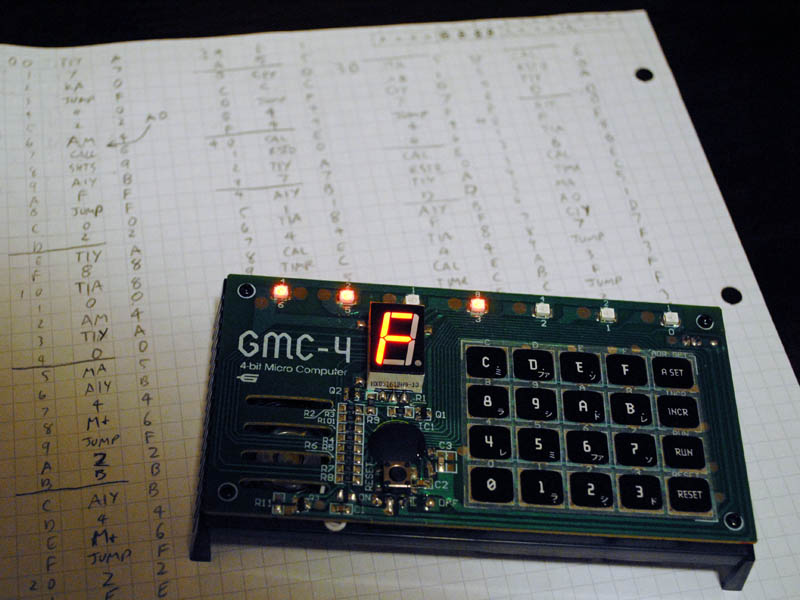 Those primitive scratchings beneath are my first working program.
Once built, the next step was to make it actually do something. I was feeling particularly masochistic, so I decided to figure it out the hard way - without the internet. Armed with a Nintendo DS and a copy of Kanji Sonomama Rakubiki Jiten I spent the next couple of hours translating the operating guide and the instruction set. Once I had a rough idea of how the thing worked and had managed to get a couple of the sample programs running, it was time to write a program for myself.
Since the GMC-4’s built-in arithmetic is limited to 4-bit addition and subtraction, I figured an achievable enough goal for an afternoon’s work would be a 16-bit adder. Five hours later, all I had was a program that thought that 1 + 1 == F. It was slow going - writing the program out on paper and then translating the mnemonics into machine code by hand. Still, I found the process perversely satisfying once everything was finally working and it reminded me of my college days when we had to do the same thing for a 6502. It took another four hours to fix all the bugs and then fit the code into memory. In the end, it exactly filled the available program memory and used 13 of the available 16 nibbles of data memory. Three nibbles to spare!
Here’s a video of the adder in action, calculating the following sums:
0x3978 + 0x2BD6 = 0x0654E
0xA5E3 + 0xD687 = 0x17C6A
Full source code is below. From left to right, the columns are as follows: code address as displayed by the binary LEDs on the system, code address in hexadecimal, operation mnemonic, opcode value, comments.
-------  00   TIY  A  ; INPUT PHASE: Init data pointer to most significant digit of first number - digits
------*  01   <7>  7  ; are read into addresses 7,6,5,4 for the first number and 3,2,1,0 for the second.
-----*-  02    KA  0  ; Wait for user input.
-----**  03  JUMP  F
----*--  04   <0>  0
----*-*  05   <2>  2
----**-  06    AM  4  ; Store and display digit.
----***  07    AO  1
---*---  08   CAL  E  ; BEEP! this both provides feedback and creates a short delay,
---*--*  09  SHTS  9  ; which prevents the press being registered multiple times.
---*-*-  0A   AIY  B  ; Decrement data pointer
---*-**  0B   <F>  F
---**--  0C  JUMP  F  ; If the pointer is still >= 0, loop again.
---**-*  0D   <0>  0
---***-  0E   <2>  2
---****  0F   TIY  A  ; Store the first carry value (which has value 0) in the location of the first output digit (address 8).
--*----  10   <8>  8
--*---*  11   TIA  8
--*--*-  12   <0>  0
--*--**  13    AM  4
--*-*--  14   TIY  A  ; Reset data pointer to point to the least significant digit of the second number.
--*-*-*  15   <0>  0
--*-**-  16    MA  5  ; MAIN LOOP: Load a digit from the first number.
--*-***  17   AIY  B
--**---  18   <4>  4
--**--*  19    M+  6  ; Add the corresponding digit of the second number.
--**-*-  1A  JUMP  F  ; Check for overflow.
--**-**  1B   <2>  2
--***--  1C   <C>  C
--***-*  1D   AIY  B  ; The addition caused no overflow, add the carry value from the previous step.
--****-  1E   <4>  4
--*****  1F    M+  6
-*-----  20  JUMP  F  ; Check for overflow again.
-*----*  21   <2>  2
-*---*-  22   <F>  F
-*---**  23    AM  4  ; Still no overflow, store a carry value of 0 in the address of the next output digit.
-*--*--  24   AIY  B
-*--*-*  25   <1>  1
-*--**-  26   TIA  8
-*--***  27   <0>  0
-*-*---  28    AM  4
-*-*--*  29  JUMP  F  ; Skip to end of the loop.
-*-*-*-  2A   <3>  3
-*-*-**  2B   <5>  5
-*-**--  2C   AIY  B  ; Overflow caused by the initial digit addition - add the carry value from the previous step.
-*-**-*  2D   <4>  4
-*-***-  2E    M+  6
-*-****  2F    AM  4  ; We can get here from either of the two possible overflow conditions,
-**----  30   AIY  B  ; store a carry value of 1 in the address of the next output digit.
-**---*  31   <1>  1
-**--*-  32   TIA  8
-**--**  33   <1>  1
-**-*--  34    AM  4
-**-*-*  35   AIY  B  ; Move on to next digit.
-**-**-  36   <8>  8
-**-***  37   CIY  D  ; Check if we've reached the last digit.
-***---  38   <4>  4
-***--*  39  JUMP  F  ; If not, run the loop again.
-***-*-  3A   <1>  1
-***-**  3B   <6>  6
-****--  3C   CAL  E  ; DISPLAY PHASE: Clear the display.
-****-*  3D  RSTO  0
-*****-  3E   TIY  A  ; Set the data pointer to point past the most significant digit of the output.
-******  3F   <D>  D
*------  40   AIY  B  ; Decrement the data pointer.
*-----*  41   <F>  F
*----*-  42   TIA  8  ; Pause for a short while.
*----**  43   <6>  6
*---*--  44   CAL  E
*---*-*  45  TIMR  C
*---**-  46    MA  5  ; Load and display the value of output digit.
*---***  47    AO  1
*--*---  48   CIY  D  ; Check if we've stepped past the least significant digit of the output.
*--*--*  49   <7>  7
*--*-*-  4A  JUMP  F  ; If so, jump back and clear the display.
*--*-**  4B   <4>  4
*--**--  4C   <0>  0
*--**-*  4D  JUMP  F  ; If not, jump back and move on to the next digit.
*--***-  4E   <3>  3
*--****  4F   <C>  C
Curtis Hoffmann has written a comprehensive description of the GMC-4 and his page also has links to a GMC-4 simulator and assembler.
One feature of the CPU that caused me trouble is that it has only one status flag, the value of which is modified by every instruction. The instruction for reading the keypad sets this flag to 0 if a key is pressed, and 1 if not; the compare instructions set it to 1 if a register is not equal to some constant, and 0 otherwise; the arithmetic instructions set the flag to 1 on overflow and 0 otherwise; all other instructions set the flag to 1. There is only one direct branch instruction and branches are only taken if the status flag is 1 at the time.
The upshot of this is that tests must be acted upon immediately, otherwise their results will be discarded as soon as the next instruction executes. Couple this with a limited instruction set and a scarcity of registers and I ended up having to duplicate many sequences of instructions. Not what you want to be doing with only 40 bytes of memory.
As an example, here’s pseudo code for adding two values stored in addresses 0 and 1, writing the 4-bit result to address 2 and the carry bit to address 3. A and Y are registers, [Y] denotes a reference to the data at address Y:
        Y  =  0
        A  = [Y]
        Y  =  1
        A += [Y]
        goto overflow     ; only taken if addition overflowed
no_overflow:
        Y  =  2
       [Y] =  A
        A  =  0
        goto store_carry  ; alway taken
overflow:
        Y  = 2
       [Y] = A
        A  = 1
store_carry:
        Y  = 3
       [Y] = A
It’s possible to remove this duplication by using some of the remaining six registers, but without any direct way to load data into any register other than A, it’s more effort (and code) that it’s worth.
Here’s another video showing the input process for a much shorter program. You can see how the binary LEDs update to show the current program address as the opcodes are entered. There’s a light show at the end as a payoff, so stick with it! (Or just skip to 1:05)
And here’s the source code:
-------  00   TIA  8  ; Register A stores the delay between each update.
------*  01   <0>  0  ; Register Y stores the current LED position.
-----*-  02   TIY  A  ; Start scrolling left.
-----**  03   <0>  0
----*--  04   CAL  E
----*-*  05  TIMR  C
----**-  06   CAL  E
----***  07  RSTR  2
---*---  08   AIY  B
---*--*  09   <3>  3
---*-*-  0A    AM  4  ; Redundant operation whose purpose is to make sure the status flag is set to 1
---*-**  0B   CAL  E  ; otherwise, this call won't get executed.
---**--  0C  SETR  1
---**-*  0D   AIY  B
---***-  0E   <E>  E
---****  0F   CIY  D
--*----  10   <4>  4
--*---*  11  JUMP  F  ; Continue scrolling left.
--*--*-  12   <0>  0
--*--**  13   <4>  4
--*-*--  14   TIY  A  ; Start scrolling right.
--*-*-*  15   <6>  6
--*-**-  16   CAL  E
--*-***  17  TIMR  C
--**---  18   CAL  E
--**--*  19  RSTR  2
--**-*-  1A   AIY  B
--**-**  1B   <D>  D
--***--  1C    AM  4  ; Redundant operation whose purpose is to make sure the status flag is set to 1
--***-*  1D   CAL  E  ; otherwise, this call call won't get executed.
--****-  1E  SETR  1
--*****  1F   AIY  B
-*-----  20   <2>  2
-*----*  21   CIY  D
-*---*-  22   <2>  2
-*---**  23  JUMP  F  ; Continue scrolling right.
-*--*--  24   <1>  1
-*--*-*  25   <6>  6
-*--**-  26  JUMP  F  ; Start scrolling left again.
-*--***  27   <0>  0
-*-*---  28   <2>  2
That’s about all I’ve done with the GMC-4 so far. It’s not much, but it’s been a lot of fun programming a bit closer to the metal for a change.